"Seeing by electricity",
Design and Work, 26 June 1880.
Cet article paru dans la revue londonienne Design and Work. A home and shop companion est une reprise de l'article "Seeing by electricity", Scientific American, June 5, 1880. Il ne comporte que de légères différences : la numérotation des illustrations a été améliorée et l'orthographe anglicisé ("disc" au lieu de "disk".) L'article était également paru dans English Mechanic and World of Science, 18 June 1880.
Voir la notice "Les propositions de George R. Carey".
Seeing by electricity.
The art of transmitting images by means of electric currents is now in about the same state of advancement that the art of transmitting speech by telephone had attained in 1876, and it remains to be seen whether it will develop as rapidly and successfully as the art of telephony. Professor Bell's announcement that he had filed at the Franklin Institute a sealed description of a method of seeing by telegraph brings to mind an invention for a similar purpose, submitted to us some months since by the inventor, Mr. Geo. R. Carey, of the Surveyors Offlice, City Hall, Boston, Mass. By consent of Mr. Carey we present herewith engravings and descriptions of his wonderful instruments.
Figs. 1 and 2 are instruments for transmitting and recording at long distances, permanently or otherwise, by means of electricity the picture of any object that may be projected by the lens of camera, fig. 1, upon its disc, P. The operation of this device depends upon the changes in. electrical conductivity produced by the action of light in the metalloid selenium. The disc, P, is drilled through perpendicularly to its face, with numerous small holes, each of which is filled partly or entirely with selenium, the selenium forming part of an electrical circuit.
The wires from the disc, P, are insulated, and are wound into a cable after leaving binding screw, B. These wires pass through disc, C (fig. 2), in the receiving instrument, at a distant point, and are arranged in the same relative position as in disc, P (fig. 1).
A chemically-prepared paper is placed between discs, C and D, for the image of any object projected upon disc, P (Fig. 1), to be printed upon.
Fig. 3 is a sectional view of fig. 2, showing wires and the chemically-prepared paper.
Fig. 5 is a sectional viev of disc, P (fig. 1), showing selenium points and conducting wires.
Fig. 6 is a sectional view of another receiving instrument with platinum or carbon points, covered with a glass cap, there being a vacuum between glass cap, D, and insulating plate or disc, C.
These points are rendered incandescent by the passage of the electrical current, thereby giving a luminous image instead of printing the same. These platinum or carbon points are arranged relatively the same as the selenium points in plate P (figs.1 and 4); each platinum or carbon point is connected with one of the wires from selenium point in disc, P (fig. 1), and forms part of an electrical circuit.
The operation of the appareils is as follows: if a white letter, A, upon a black ground be projected upon disc, P (fig.1), all parts of disc will be dark, excepting where the letter A is, when it will be light ; and the selenium points in the light will allow the electric current to pass, and if the wires leading, from disc, P (fig. 1) are arranged in the same relative position when passing through disc, C (fig. 2), the electricity will print upon the chemically-prepared paper between C and D (fi,. 2), a copy of the letter, A, as projected upon disc, P (Fig. 1). By this means any object so projected and so transmitted will be reproduced in a manner similar to that by which the letter A was reproduced.
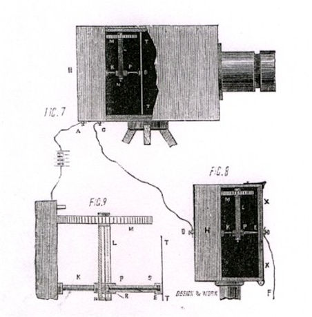
Figs. 7 and 8 are instruments for transmitting and recording by means of electricity the picture of any object that may be projected upon the glass plate at T T (fig. 7), by the camera lens. The operation of these instruments depends upon the changes in electrical conductivity produced by the action of light on the metalloid selenium.
The clockwork revolves the shaft, K, causing the arm, L, and wheel, M, to describe at circle of revolution. The screw, S, being fastened firmly to wheel, M, revolves as wheel, M, revolves on its axis, thus drawing the sliding piece, P, and selenium point, disc, or ring, B, towards the wheel, M, see fig. 9. These two motions cause the point, disc, or ring, B, to describe a spiral line upon the glass, T T, thus passing over every part of the picture projected upon glass, T T.
The selenium point, disc, or ring will allow the electrical current to fIow through it in proportion to the intensity of the lights and shades of the picture projected upon glass plate, T T.
The electric currents enter camera at A, and pass directly to the selenium point, disc, or ring, B, thence through the sliding piece, P, and shaft, K, by an insulated wire to binding screw, C (Fig.7), from the screw by wire to binding screw, D (Fig.8), through shaft, K, and sliding piece, P, to point, E (fig.8), then through the chemically-prepared paper placed against the inner surface of the metallic plate, X X, by wire, to the ground, thus completing the circuit and leaving upon the above-mentionned chemically-prepared paper an image or permanent impression of any object projected upon the glass plate, T T, by the camera lens.
Fig.8 is the receiving instrument, which has a clock movement similar to that of fig.7, with the exception of the metallic point, E, in place of the selenium point, disc or ring (fig.7), at B.
Fig. 9 is an enlarged view of clock-work and machinery shown in figs. 7 and 8.